CNC – Module 2.3
Module 1 | Module 2 | Module 3
Module 2.1 | Module 2.2 | Module 2.3 | Module 2.4 | Module 2.5 | Module 2.6 | Module 2.7
Locate Your Workpiece
You need to determine the location and orientation of your workpiece with repect to the machine coordinate system. To accomplish this, you will need to load the edge finder tool into the spindle.
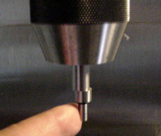 1. Pushing the edge finder tip to one side so that it will wobble when it is spinning. |
 2. Enter the MDI mode and enter S1000 MO3 to begin CW rotation of the edge finder. |
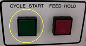 3. Close the doors and push CYCLE START to start the spindle. |
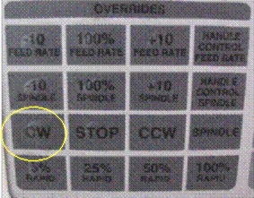
4. At this point, you can open the doors and the edge finder will keep spinning but at a slower speed. From now on, you can just start and stop the spindle by pushing either STOP or CW on the OVERRIDES keypad. From this point on, you will most likely be working with the doors open so that you can see the edge finder clearly. However, you can keep the doors closed if you can see the workpiece area clearly. (This will often depend on how clean the front windows are!) You will need to be very careful to keep all body parts and clothing clear of the spindle. Even though an edge finder does not have cutting surfaces, you could be tangled in the spindle. |
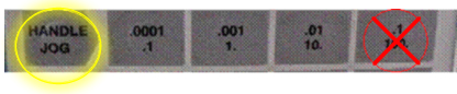 5. Touch the sides of your stock (vice, etc.) with the edge finder corresponding to the X or Y zero by using the HANDLE JOG mode to move the axes. NOTE: You should not use the 0.1″ increment when edge finding. This allows the axes to move very quickly and you could get injured or damage the edge finder. |
 6. As you approach the workpiece, you will need to use smaller and smaller increments on the HANDLE JOG buttons, in order to precisely contact the side of the workpiece. Good practice is to jog the edge finder to about ¼” from the workpiece face, then begin to slowly jog at either 0.001″ or 0.0001″ increments as you approach the face of the workpiece. |
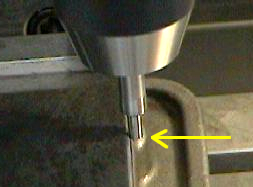
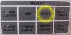 7. After the edge finder has stopped wobbling, continue to jog the edge finder at 0.0001″ until it JUST pops off center.(This may take a little practice). Once you have successfully positioned the edge finder, push the OFSET button and then page UP/DOWN until you find the screen “WORK ZERO OFFSET”. |
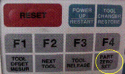 8. With G54 (G55, G56, etc.) highlighted under either X or Y, depending on which surface you are touching, push the PART ZERO SET button. This will enter the location for that work coordinate (X or Y). The cursor will automatically move to the next offset to the right, but you need to move the cursor back to the one you just entered. |
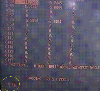 9. What you just stored in the offset is the location of the EDGE of the edge finder, not the center of the spindle. You need to add or subtract (depending on the direction the spindle is traveling when you touched the surface) the radius of the edge finder tool. Most of the edge finders will have a radius of 0.1″. EXAMPLE: If you are touching the front face of your stock (the side facing you) and you want to set the Y-OFFSET, then you need to ADD 0.1″ to the number that was entered when you pushed the PART ZERO SET button. As shown in the lower left corner of the display, 0.1″ will be subtracted from the x-offset coordinate. |
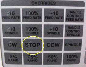 10. Jog the edge finder away from the face and push STOP on the Overrides keypad to stop the spindle rotation. |
 11. Return to step 1 and set the remaining offset (X or Y). (In order to get the spindle rotating again after pushing the edge finder with your finger, you can simply push the CW button with the doors open and it will begin to spin again) |