CNC – Module 1.2
Module 1 | Module 2 | Module 3
Module 1.1 | Module 1.2
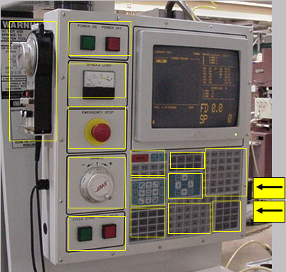
CNC Controller
This is the controller for the machine and is the most complicated part of the machine. From here you can load programs, write programs, turn coolant on and off, jog the machine tool and table and change parameters for the machine.
We’ll make it easier on you by going over each part of the controller. Descriptions for the highlighted parts are listed below.
 Okay, this is an easy one. But before the power will come on you’ll need to flip the main switch on the back of the machine and maybe even the breaker box to the machine itself. |
 This meter tells you the load on the spindle when it is running. It is not uncommon to see the needle go briefly into the yellow or red areas, especially when the spindle just starts up or changes rpm. If the spindle load becomes too high during machining, you might need to make some changes. Refer to the manual for the machine to see what to do when spindle loads get too high. |
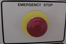 Either you or your partner should be within arm’s reach of the Emergency Stop when running the machine. This one is self-explanatory. Be ready to hit this button if something seriously goes wrong. We also use it before powering down the machine, so you’ll most likely have to twist and reset it when you power up the machine. If you just need to stop the movement of the axes of the machine, we usually just hit the “Feed Hold” button. However, the “Feed Hold” button does NOT stop the spindle from spinning so you can still have a problem or get hurt. |
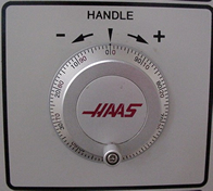 This is the JOG HANDLE for the 3,4, or 5 axes of your machine. In the jog mode you can turn this knob to move the axes. As you can see, the knob has 100 “notches” around it. For each “click” the axis will move the amount you specify on the keypad beside the “Handle Jog” button. (0.1″, 0.01″, 0.001″, or 0.0001″). There is a similar jog handle on the optional remote jog controller that is hanging on the left side of the controller. |
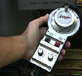 On some machines, there may be a remote jog handle that can be more convenient to use. It will most likely be hanging on the side of the controller. It has buttons and knobs to select the axis you want to jog, and even has a cycle start and feed hold button. These functions will be explained later. |
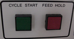 Before pushing Cycle Start, you must ALWAYS make sure all foreign objects and more importantly, PEOPLE are clear from the spindle and the doors are closed. Cycle Start and Feed Hold are two very important buttons, and you’ll probably have one finger on each when running your first programs. Cycle Start starts your program running as long as you have no errors and the doors are closed. The Feed Hold button will stop the motion of all the axes but will allow the spindle to keep spinning. When you run a new and untested program, keep a finger on the feed hold button so that you have at least a chance of stopping the tool from colliding with anything. You can simply hit Cycle Start again to keep moving, if everything looks okay. Before pushing cycle start for the first time, you will need to review and verify your entire program. You should also decrease the feed, speed, and rapid travel for a new untested program. |
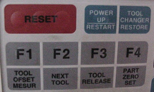 We’ll focus on only a few of these buttons. The RESET button is used during power up and other times to clear warnings from the screen or to restart a program. The POWER UP/ RESTART button is used every time when we power up the machine. The TOOL OFSET MESUR and PART ZERO SET buttons we will use to set our tools and to setup our work coordinates, respectively. To find out more about the other buttons, refer to the HAAS manual. |
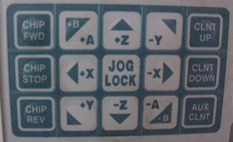 These buttons are used to manually control the chip auger, the optional programmable coolant nozzle, and the spindle location. You can use the 9 jog buttons in the center to move the spindle along the axes of the machine. If you push a button once, the spindle will move will move along that axis based on the Jog Handle value. If you push and hold one of the buttons, that axis will move at a rate based on the amount you choose beside the HANDLE JOG button (0.1″, 0.01″, 0.001″, or 0.0001″). If the JOG LOCK key is pressed before a key for an axis, that axis will move continuously without holding the button. Pushing the JOG LOCK button again will stop the motion. Note how there are both + and – directional buttons for each axis. Be careful if you use JOG LOCK, because the machine will just continue to move the table until it reaches its limits. |
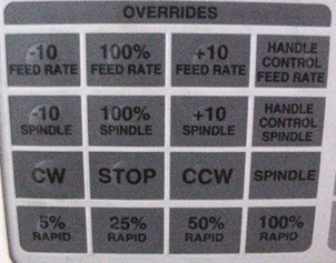 These are the OVERRIDE buttons, which are very important, especially when running a new program. For example, if you are running new program, you might want to bring all your feeds, speeds and rapid travels down to a very slow pace so that you can stop any collisions or breakage by using the FEED HOLD or the E-STOP. Most important, you will want to bring your RAPID travel speed down to probably 5% for the first run. There are also buttons for turning the spindle on or off manually (CW, STOP, OR CCW). If for example, you hit FEED HOLD, you could then stop the spindle with the STOP button. Before hitting CYCLE START again, you would need to hit CW again to start the spindle. |
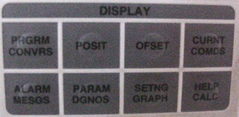 Under the display window we’ll look at a few important buttons. The OFSET button will display tool offsets and work coordinates. If you push the PAGE UP/DOWN buttons, you will scroll through all of the offset screens. In order to run a program, you will first hit the MEM button (under misc. keys, explained later) then you will hit the CURNT COMDS button shown above. You may need to hit the ALARM MESGS button if you get an alarm warning on the screen and want to know what happened. Pushing the RESET button will clear any alarms that have been resolved. |
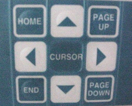 Use the cursor pad to navigate around the display. Push the arrows to move through your NC code. When running a program, you can push the up or down arrows to change the list of coordinates in the upper right of the screen. In other words, you can track where the tool is or how far it has to go for each line of code. The PAGE UP/DOWN buttons are used just like on a keyboard to quickly scroll through your program. HOME and END are used to go to the beginning or end of your program. |
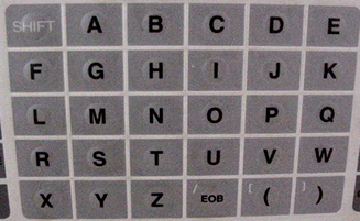 You can use the alphabetic keypad to write your NC code. |
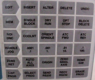 This keypad has a lot of functions, so we’ll examine each row. There are 6 rows of keys. Pushing the key on the far left activates each row. For example, if you want to turn the coolant on, you need to push MDI/DNC (row 3) to put the controller in the right mode and then push the COOLNT button to turn it on. If you push a button before hitting the modekey, the message – WRONG MODE – will appear on the display. Row 1 – EDITIn this mode you can edit an NC program, either under the current commands window, or if you are writing code manually under the MDI mode. The cursor will highlight one piece of code on the screen. If you want to insert code before something on the display type it in and push INSERT. This will insert your code before the highlighted code. If you want to change it, just type in the new code and hit ALTER, which will replace what was highlighted. DELETE will remove the highlighted code. UNDO is self-explanatory. Row 2 – MEMPushing MEM will bring your current program up in memory. Following with a push of the CURNT COMDS button will set up the controller for you to hit CYCLE START. If you don’t go into MEM mode and then hit the CURNT COMDS button, hitting CYCLE START will do nothing. The only button you should likely use is SINGLE BLOCK. Pushing this button before running a program will step through the program one line at a time and pause after each line. You have to continue to push CYCLE START to step through your program. This is good if you are running some untested code and you are unsure if it will run correctly. Row 3 – MDI/DNCPushing the MDI/DNC button toggle between two modes, manual data input (MDI) and direct numerical control (DNC). We will only talk about MDI since you will usually use this mode. The MDI mode opens up a scratch pad. Use the pad to to write simple lines of NC code that will be executed by pushing CYCLE START. As an example, you may want to retrieve a particular tool. You can push the mode button once and type T6 MO6 [enter]. This line of code will appear on the upper left. With the doors closed, pushing CYCLE START will initiate a tool change and retrieve tool number 6. Another example is if you need to spin an edge finder. You would type S1000 MO3 [enter]. This would start the spindle spinning at 1000 rpm in a CW rotation. Other common buttons you might push are the COOLNT, ATC FWD, and ATC REV buttons. The COOLNT button turns the coolant on and off. The ATC FWD and REV buttons automatically initiate a tool change to the next or previous tool in the carousel. WARNING: a tool change will automatically start when you press these buttons; EVEN IF THE DOOR is open. Be sure that people are clear from the machine before pushing either of these buttons. Row 4 – HANDLE JOGUse this mode to manually move the 3,4, or 5 axes of the machine. The increments written on the buttons in this row tell you how far the axis will move with each click of the handle jog wheel. This mode also allows you to push the buttons around the JOG LOCK button to move the axes. This was explained above. Row 5 – ZERO RETThis mode is typically used before powering down. When you push the HOME G28 button in this mode, each axis will move to the home position rapidly. Again, be sure nobody is in the way and all loose fixtures, tools, etc. are not going to collide when the axes home themselves. It is good practice to home the axes before powering down the machine. Row 6 – LIST PROGThis mode brings up all programs in the memory of the controller. Pushing SELECT PROG will load the currently highlighted program. |
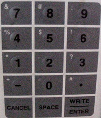 Use this keypad along with the alphabetic keypad to write programs or to enter values in the offset pages. CANCEL is used to backspace when manually typing code. The WRITE/ENTER button inserts your code on the scratch pad or enters your changes into the work or tool offsets. For example, if you used a 0.003″ sheet of paper to set a tool against the face of your stock, you would type in ” – 0.003″ [enter] and 0.003 will be subtracted from the highlighted coordinate for the offset. (If you need to add to the highlighted offset, just type in the additional amount and hit [enter] since there is no “+” button.) |
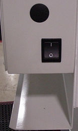 On the side of the controller is a switch to turn the interior light on. |
 A very important part of understanding the operation of any machine is of course, the USER MANUAL. Since we are not going to cover everything you need to know about CNC machines, you may want to review the topics in the manual. This is also a great reference for problem solving when running the machine. |